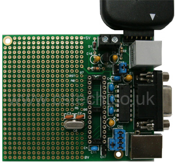
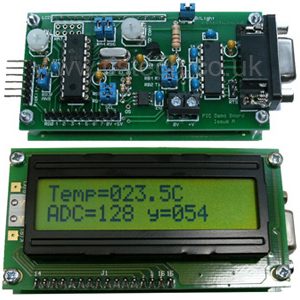
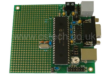
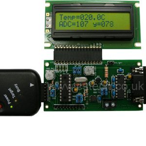
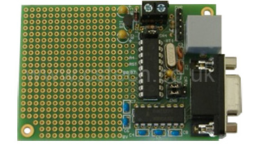
Development board for 28 pin Pic Microcontrollers
PicKit2/3 and ICD compatible
Ideal for USB PICs
Works with many 28 pin PICs
On board RS232 level converter
£13.49
Compatible PICs include 16F876, 18F252, 18F2520 and 18F2550.
Ideal for the PIC18F2550 (USB) which is available on our components section.
High quality Gold Plated PTH (plated through hole) PCB 1.6mm FR4 (Fiberglass) board with large prototyping area with pads on both sides of the board.
You can select the 5V power supply to come from the on-board regulator, Microchip PicKit/ICD or USB.
The +5V and 0V power rails are extended along the top & bottom edges of the board for easy access.
CONNECTIONS
An onboard RS232 level converter buffers the PIC UART to/from the 9 pin D connector, which is tracked for connection to a PC serial port. The RTS & CTS lines are also buffered and brought to CN9. The RS232 interface can be disconnected from the PIC using jumper links in CN6.
You can also disconnect the USB socket from the PIC using jumper links in CN6, useful if you’re using a non USB PIC, and powering from a USB cable.
A 6 pin programming header is also provided to allow in-circuit programming from the PicKit2 and PicKit3 programmers.
Microchip ICD2 and ICD3 programmers can be connected via the ICD connector.
The 470nf USB decoupling capacitor can be disconnected from the PIC using CN7.
CRYSTAL
You can have a 4MHz, 10MHz or 20MHz crystal. If you would like the 10MHz or 20MHz please specify when ordering, otherwise 4MHz will be supplied. We use 4MHz for USB with the 18F2550. The 4MHz crystal is multiplied to 96MHz inside the PIC and then divided to 48MHz for the USB peripheral and microcontroller core clocks. Many other crystal and divider combinations are possible, please see the PIC data sheet.
WHAT’S IN THE BOX?
Gold Plated PCB, kit components. See the PDF for instruction details and component list.

